Not affiliated with or endorsed by the FCC, NCVEC, ARRL or any VEC. Questions are the NCVEC pools word for word (public domain); explanations are our own. Exam rules and fees can change: check with your VE team.
E5C: Coordinate systems and phasors in electronics: rectangular coordinates; polar coordinates; phasors; logarithmic axes
Group E5C of the Amateur Extra pool (2024–2028) has 12 active questions. One of them is on every Amateur Extra exam. Each is shown word for word; open it to see the correct answer and our explanation.
E5C01
Which of the following represents pure capacitive reactance of 100 ohms in rectangular notation?
A 0 - j100
B 0 + j100
C 100 - j0
D 100 + j0
Show the answer and explanation
Correct answer: A. 0 - j100
Why A is right. A. Pure capacitive reactance has no resistance (real part 0) and a negative imaginary part, so it is 0 - j100.
Rectangular notation writes impedance as R + jX. The first number is resistance. The j term is reactance: plus for inductive, minus for capacitive. A pure capacitive reactance of 100 ohms is zero resistance and -j100.
Why not B? +j100 would be inductive reactance.
E5C02
How are impedances described in polar coordinates?
A By X and R values
B By real and imaginary parts
C By magnitude and phase angle
D By Y and G values
Show the answer and explanation
Correct answer: C. By magnitude and phase angle
Why C is right. C. Polar form gives an impedance as a length, its magnitude in ohms, and an angle, its phase.
Picture the impedance as an arrow from the origin of a graph. Its length is the magnitude, and its angle from the horizontal axis is the phase angle, for example 100 ohms at 30 degrees. Rectangular form describes the same point by its horizontal and vertical parts instead.
Why not B? Real and imaginary parts are the rectangular form.
E5C03
Which of the following represents a pure inductive reactance in polar coordinates?
A A positive 45 degree phase angle
B A negative 45 degree phase angle
C A positive 90 degree phase angle
D A negative 90 degree phase angle
Show the answer and explanation
Correct answer: C. A positive 90 degree phase angle
Why C is right. C. A pure inductive reactance points straight up on the impedance graph, an angle of +90 degrees.
In polar form, the angle shows the balance of resistance and reactance. Pure resistance sits at 0 degrees. Pure inductive reactance has no resistance, so it lies on the positive vertical axis at +90 degrees. Pure capacitive reactance lies at -90 degrees.
Why not D? -90 degrees is pure capacitive reactance.
E5C04
What type of Y-axis scale is most often used for graphs of circuit frequency response?
A Linear
B Scatter
C Random
D Logarithmic
Show the answer and explanation
Correct answer: D. Logarithmic
Why D is right. D. Frequency response graphs usually use a logarithmic Y-axis, often in decibels, so large and tiny responses fit on one chart.
A filter may pass one frequency at full strength and cut another a million times. On a linear scale the small values would be squashed against the axis. A logarithmic scale gives equal space to each factor of ten, so both show clearly. Decibels are a logarithmic unit.
Why not A? A linear scale flattens small values, hiding how well a filter rejects signals.
E5C05
What kind of diagram is used to show the phase relationship between impedances at a given frequency?
A Venn diagram
B Near field diagram
C Phasor diagram
D Far field diagram
Show the answer and explanation
Correct answer: C. Phasor diagram
Why C is right. C. A phasor diagram draws each impedance as an arrow whose angle shows its phase, so you can compare them at one frequency.
A phasor is an arrow standing for a sine-wave quantity: its length is the size and its angle is the phase. Resistance points along the horizontal axis, inductive reactance up and capacitive reactance down. Adding the arrows tip to tail gives the total impedance.
Why not A? A Venn diagram shows overlapping groups, not phase.
E5C06
What does the impedance 50 - j25 ohms represent?
A 50 ohms resistance in series with 25 ohms inductive reactance
B 50 ohms resistance in series with 25 ohms capacitive reactance
C 25 ohms resistance in series with 50 ohms inductive reactance
D 25 ohms resistance in series with 50 ohms capacitive reactance
Show the answer and explanation
Correct answer: B. 50 ohms resistance in series with 25 ohms capacitive reactance
Why B is right. B. The real part, 50, is resistance; the negative j part, 25, is capacitive reactance.
In R ± jX form, the number without j is resistance in ohms. The j number is reactance, and its sign tells the type: plus for inductive, minus for capacitive. So -j25 means 25 ohms of capacitive reactance in series with the 50 ohms.
Why not A? Inductive reactance would be written +j25.
E5C07
Where is the impedance of a pure resistance plotted on rectangular coordinates?
A On the vertical axis
B On a line through the origin, slanted at 45 degrees
C On a horizontal line, offset vertically above the horizontal axis
D On the horizontal axis
Show the answer and explanation
Correct answer: D. On the horizontal axis
Why D is right. D. Pure resistance has no reactance, so its point sits on the horizontal (resistance) axis.
On a rectangular impedance graph, the horizontal axis is resistance and the vertical axis is reactance. A pure resistor has zero reactance, so its vertical value is zero. A 50-ohm resistor plots at 50 on the horizontal axis.
Why not A? The vertical axis holds pure reactance with no resistance.
E5C08
What coordinate system is often used to display the phase angle of a circuit containing resistance, inductive, and/or capacitive reactance?
A Maidenhead grid
B Faraday grid
C Elliptical coordinates
D Polar coordinates
Show the answer and explanation
Correct answer: D. Polar coordinates
Why D is right. D. Polar coordinates show the phase angle directly as the angle of a line from the origin.
An impedance in polar form is a magnitude and an angle. The angle is the phase difference between voltage and current: positive for inductive circuits, negative for capacitive, and zero for pure resistance. Plotting it this way lets you read the phase angle at a glance.
Why not A? The Maidenhead grid locates stations on Earth's surface.
E5C09
When using rectangular coordinates to graph the impedance of a circuit, what do the axes represent?
A The X axis represents the resistive component, and the Y axis represents the reactive component
B The X axis represents the reactive component, and the Y axis represents the resistive component
C The X axis represents the phase angle, and the Y axis represents the magnitude
D The X axis represents the magnitude, and the Y axis represents the phase angle
Show the answer and explanation
Correct answer: A. The X axis represents the resistive component, and the Y axis represents the reactive component
Why A is right. A. On a rectangular impedance graph, resistance runs along the horizontal X axis and reactance up and down the Y axis.
Each impedance R + jX becomes a point: move R to the right, then move X up for inductive or down for capacitive. Resistance in ordinary passive circuits is never negative, so these points sit to the right of the vertical axis.
Why not C? Magnitude and angle are polar coordinates, not rectangular.
E5C10
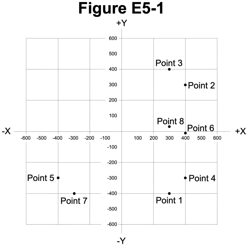
Which point on Figure E5-1 best represents the impedance of a series circuit consisting of a 400-ohm resistor and a 38-picofarad capacitor at 14 MHz?
Figure E5-1
A Point 2
B Point 4
C Point 5
D Point 6
Show the answer and explanation
Correct answer: B. Point 4
Why B is right. B. The circuit is 400 ohms of resistance with about 299 ohms of capacitive reactance, which plots at Point 4.
In Figure E5-1, resistance runs along the horizontal axis and reactance along the vertical axis, with capacitive reactance below the horizontal axis. Point 4 sits 400 ohms to the right and 300 ohms down, in the lower right quarter. That matches 400 - j299.
XC = 1 / (2π × f × C)
XC = 1 / (2 × 3.1416 × 14,000,000 Hz × 38 × 10^-12 F)
XC = 1 / 0.003343 = 299 ohms
Z = 400 - j299 ohms: 400 to the right, 299 down
= 400 - j299 ohms, Point 4
Why not A? Point 2 is 400 ohms right and 300 up, which would mean inductive reactance.
E5C11
Which point in Figure E5-1 best represents the impedance of a series circuit consisting of a 300-ohm resistor and an 18-microhenry inductor at 3.505 MHz?
Figure E5-1
A Point 1
B Point 3
C Point 7
D Point 8
Show the answer and explanation
Correct answer: B. Point 3
Why B is right. B. The circuit is 300 ohms of resistance with about 396 ohms of inductive reactance, which plots at Point 3.
In Figure E5-1, inductive reactance is plotted above the horizontal resistance axis. Point 3 is in the upper right quarter, 300 ohms to the right and 400 ohms up, the closest match to 300 + j396.
XL = 2π × f × L
XL = 2 × 3.1416 × 3,505,000 Hz × 18 × 10^-6 H
XL = 396 ohms
Z = 300 + j396 ohms: 300 to the right, 396 up
= 300 + j396 ohms, Point 3
Why not A? Point 1 is 300 right and 400 down, which would mean capacitive reactance.
E5C12
Which point on Figure E5-1 best represents the impedance of a series circuit consisting of a 300-ohm resistor and a 19-picofarad capacitor at 21.200 MHz?
Figure E5-1
A Point 1
B Point 3
C Point 7
D Point 8
Show the answer and explanation
Correct answer: A. Point 1
Why A is right. A. The circuit is 300 ohms of resistance with about 395 ohms of capacitive reactance, which plots at Point 1.
Figure E5-1 places capacitive reactance below the horizontal resistance axis. Point 1 is in the lower right quarter, 300 ohms to the right and 400 ohms down, the closest point to 300 - j395.
XC = 1 / (2π × f × C)
XC = 1 / (2 × 3.1416 × 21,200,000 Hz × 19 × 10^-12 F)
XC = 1 / 0.002531 = 395 ohms
Z = 300 - j395 ohms: 300 to the right, 395 down
= 300 - j395 ohms, Point 1
Why not B? Point 3 is the mirror position above the axis, which would mean inductive reactance.