Not affiliated with or endorsed by the FCC, NCVEC, ARRL or any VEC. Questions are the NCVEC pools word for word (public domain); explanations are our own. Exam rules and fees can change: check with your VE team.
E7G: Operational amplifiers: characteristics and applications
Group E7G of the Amateur Extra pool (2024–2028) has 12 active questions. One of them is on every Amateur Extra exam. Each is shown word for word; open it to see the correct answer and our explanation.
E7G01
What is the typical output impedance of an op-amp?
A Very low
B Very high
C 100 ohms
D 10,000 ohms
Show the answer and explanation
Correct answer: A. Very low
Why A is right. A. The output stage is built to drive loads without its voltage sagging, and negative feedback lowers its effective output impedance even further.
Low output impedance means the output voltage hardly changes when a load is connected. In most op-amp circuits, feedback brings the effective value down to a few ohms or less. In the ideal model it is zero.
Why not B? High output impedance would make the output drop under load, the opposite of what op-amps are built for.
E7G02
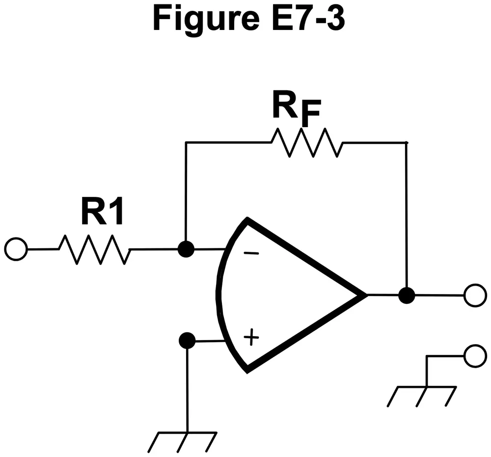
What is the frequency response of the circuit in E7-3 if a capacitor is added across the feedback resistor?
Figure E7-3
A High-pass filter
B Low-pass filter
C Band-pass filter
D Notch filter
Show the answer and explanation
Correct answer: B. Low-pass filter
Why B is right. B. A capacitor across the feedback resistor lowers the feedback impedance at high frequencies, cutting the gain there.
In Figure E7-3, RF is the zigzag resistor from the op-amp's output back to its minus input, and gain is RF divided by R1. A capacitor across RF has reactance that falls as frequency rises. At low frequencies RF sets the gain; at high frequencies the capacitor bypasses RF and the gain drops, so low frequencies pass.
Why not A? The capacitor reduces high-frequency gain, so highs are cut, not passed.
E7G03
What is the typical input impedance of an op-amp?
A 100 ohms
B 10,000 ohms
C Very low
D Very high
Show the answer and explanation
Correct answer: D. Very high
Why D is right. D. Op-amp inputs draw almost no current, so they present a very high input impedance.
Bipolar op-amps have input impedances of a megohm or more, and FET-input types go far higher. The op-amp therefore barely loads whatever drives it. In ideal circuit analysis the input current is taken as zero.
Why not C? Low input impedance would load the source, which op-amps are designed to avoid.
E7G04
What is meant by the term “op-amp input offset voltage”?
A The output voltage of the op-amp minus its input voltage
B The difference between the output voltage of the op-amp and the input voltage required in the immediately following stage
C The differential input voltage needed to bring the open loop output voltage to zero
D The potential between the amplifier input terminals of the op-amp in an open loop condition
Show the answer and explanation
Correct answer: C. The differential input voltage needed to bring the open loop output voltage to zero
Why C is right. C. Small mismatches in the input transistors act like a tiny built-in voltage between the inputs; the outside voltage that cancels it and zeroes the open-loop output is the offset.
Tiny mismatches between the input transistors mean that, with the inputs tied together, the huge open-loop gain still drives the output toward one supply limit. A few millivolts or less across the inputs brings it back to zero; that voltage is the offset. High-gain DC circuits are most affected.
Why not A? Output minus input is a voltage difference across the whole amplifier, not an input property.
E7G05
How can unwanted ringing and audio instability be prevented in an op-amp audio filter?
A Restrict both gain and Q
B Restrict gain but increase Q
C Restrict Q but increase gain
D Increase both gain and Q
Show the answer and explanation
Correct answer: A. Restrict both gain and Q
Why A is right. A. High gain and high Q both push an active filter toward ringing and oscillation, so both should be kept modest.
Q describes how sharp and resonant a filter is. A high-Q filter stores energy and keeps ringing after a sudden sound. Extra gain sends more signal around the feedback loop, moving the circuit closer to oscillating on its own. Moderate values give a stable, clean response.
Why not D? Raising both gain and Q makes ringing and instability worse.
E7G06
What is the gain-bandwidth of an operational amplifier?
A The maximum frequency for a filter circuit using that type of amplifier
B The frequency at which the open-loop gain of the amplifier equals one
C The gain of the amplifier at a filter’s cutoff frequency
D The frequency at which the amplifier’s offset voltage is zero
Show the answer and explanation
Correct answer: B. The frequency at which the open-loop gain of the amplifier equals one
Why B is right. B. Above a low corner, open-loop gain falls in step with frequency, so gain times frequency stays constant and equals the frequency where the gain reaches 1.
Above a low corner frequency, open-loop gain falls in proportion to frequency, so gain times frequency stays about constant. A part with 1 MHz gain-bandwidth can give a gain of 10 up to about 100 kHz, or a gain of 100 up to about 10 kHz.
Why not D? Offset voltage is a DC error and is not tied to a frequency.
E7G07
What voltage gain can be expected from the circuit in Figure E7-3 when R1 is 10 ohms and RF is 470 ohms?
Figure E7-3
A 0.21
B 4700
C 47
D 24
Show the answer and explanation
Correct answer: C. 47
Why C is right. C. In this inverting circuit the gain size equals the feedback resistor divided by the input resistor, and 470 divided by 10 is 47.
In Figure E7-3, input resistor R1, a zigzag, runs from the input to the op-amp's minus input, and feedback resistor RF runs from the output back to that same minus input, while the plus input goes to ground. Feedback holds the minus input near 0 volts, so all current through R1 must also flow through RF.
|G| = RF / R1
|G| = 470 ohms / 10 ohms
= 47
Why not B? 4700 is the product of the two resistances, not their ratio.
E7G08
How does the gain of an ideal operational amplifier vary with frequency?
A It increases linearly with increasing frequency
B It decreases linearly with increasing frequency
C It decreases logarithmically with increasing frequency
D It does not vary with frequency
Show the answer and explanation
Correct answer: D. It does not vary with frequency
Why D is right. D. An ideal op-amp is defined to have unlimited gain and bandwidth, so its gain is the same at every frequency.
Real op-amps lose gain as frequency rises, which is what gain-bandwidth describes. The ideal model removes such limits so circuit behavior depends only on the parts around the op-amp. It is a useful starting point for design.
Why not B? Gain falling with frequency describes real op-amps, not the ideal one.
E7G09
What will be the output voltage of the circuit shown in Figure E7-3 if R1 is 1,000 ohms, RF is 10,000 ohms, and 0.23 volts DC is applied to the input?
Figure E7-3
A 0.23 volts
B 2.3 volts
C -0.23 volts
D -2.3 volts
Show the answer and explanation
Correct answer: D. -2.3 volts
Why D is right. D. The gain is 10, and the inverting circuit flips the sign, so 0.23 volts in gives minus 2.3 volts out.
In Figure E7-3, input resistor R1, a zigzag, runs from the input to the op-amp's minus input, and feedback resistor RF runs from the output back to that same minus input, while the plus input goes to ground. A positive input pushes current toward the minus input, so the output must go negative to pull that current away through RF.
Vout = -(RF / R1) x Vin
Vout = -(10,000 ohms / 1,000 ohms) x 0.23 V
Vout = -10 x 0.23 V
= -2.3 volts
Why not B? 2.3 volts is the right size but the wrong sign; this circuit inverts.
E7G10
What absolute voltage gain can be expected from the circuit in Figure E7-3 when R1 is 1,800 ohms and RF is 68 kilohms?
Figure E7-3
A 1
B 0.03
C 38
D 76
Show the answer and explanation
Correct answer: C. 38
Why C is right. C. Absolute gain is RF divided by R1, and 68,000 divided by 1,800 is about 38.
Change kilohms to ohms first: 68 kilohms is 68,000 ohms. In Figure E7-3, input resistor R1, a zigzag, runs from the input to the op-amp's minus input, and feedback resistor RF runs from the output back to that same minus input, while the plus input goes to ground. Absolute gain ignores the minus sign from inversion.
What absolute voltage gain can be expected from the circuit in Figure E7-3 when R1 is 3,300 ohms and RF is 47 kilohms?
Figure E7-3
A 28
B 14
C 7
D 0.07
Show the answer and explanation
Correct answer: B. 14
Why B is right. B. Absolute gain is RF divided by R1, and 47,000 divided by 3,300 is about 14.
Change kilohms to ohms first: 47 kilohms is 47,000 ohms. In Figure E7-3, input resistor R1, a zigzag, runs from the input to the op-amp's minus input, and feedback resistor RF runs from the output back to that same minus input, while the plus input goes to ground. Absolute gain ignores the minus sign from inversion.
A A high-gain, direct-coupled differential amplifier with very high input impedance and very low output impedance
B A digital audio amplifier whose characteristics are determined by components external to the amplifier
C An amplifier used to increase the average output of frequency modulated amateur signals to the legal limit
D A RF amplifier used in the UHF and microwave regions
Show the answer and explanation
Correct answer: A. A high-gain, direct-coupled differential amplifier with very high input impedance and very low output impedance
Why A is right. A. An op-amp amplifies the voltage difference between its two inputs, down to DC, with enormous gain, while barely loading its source and easily driving its load.
Direct-coupled means there are no capacitors between stages, so DC is amplified as well as AC. Open-loop gain is often 100,000 or more. External resistors and capacitors set the actual gain or filter shape. The name comes from early use doing math operations in analog computers.
Why not B? Op-amps are analog devices, not digital audio amplifiers.