Not affiliated with or endorsed by the FCC, NCVEC, ARRL or any VEC. Questions are the NCVEC pools word for word (public domain); explanations are our own. Exam rules and fees can change: check with your VE team.
G7A: Power supplies; schematic symbols
Group G7A of the General pool (2023–2027) has 13 active questions. One of them is on every General exam. Each is shown word for word; open it to see the correct answer and our explanation.
G7A01
What is the function of a power supply bleeder resistor?
A It acts as a fuse for excess voltage
B It discharges the filter capacitors when power is removed
C It removes shock hazards from the induction coils
D It eliminates ground loop current
Show the answer and explanation
Correct answer: B. It discharges the filter capacitors when power is removed
Why B is right. B. The resistor sits across the filter capacitors, so their stored charge always has a path to drain away once the supply is off.
Large filter capacitors can hold a dangerous voltage long after the plug is pulled. The bleeder wastes a tiny current all the time, but it makes servicing the supply much safer.
Why not A? A fuse opens on too much current; a bleeder never opens and does not protect against overvoltage.
G7A02
Which of the following components are used in a power supply filter network?
A Diodes
B Transformers and transducers
C Capacitors and inductors
D All these choices are correct
Show the answer and explanation
Correct answer: C. Capacitors and inductors
Why C is right. C. Capacitors and inductors smooth the pulsing output of the rectifier.
After the diodes, the voltage still rises and falls in pulses. A capacitor stores charge on each peak and releases it in the dips. An inductor, also called a choke, resists quick changes in current. Together they turn the bumpy output into steady DC.
Why not A? Diodes are the rectifier that comes before the filter, not part of the filter itself.
G7A03
Which type of rectifier circuit uses two diodes and a center-tapped transformer?
A Full-wave
B Full-wave bridge
C Half-wave
D Synchronous
Show the answer and explanation
Correct answer: A. Full-wave
Why A is right. A. Two diodes on a center-tapped winding make a full-wave rectifier.
The center tap splits the transformer secondary into two halves. On one half of each AC cycle, one diode conducts; on the other half, the second diode conducts. Both halves of the wave reach the load, so it is full-wave.
Why not B? A bridge rectifier uses four diodes and does not need a center tap.
G7A04
What is characteristic of a half-wave rectifier in a power supply?
A Only one diode is required
B The ripple frequency is twice that of a full-wave rectifier
C More current can be drawn from the half-wave rectifier
D The output voltage is two times the peak input voltage
Show the answer and explanation
Correct answer: A. Only one diode is required
Why A is right. A. It uses only one half of each AC cycle, and one diode pointing one way is enough to pass that half and block the other.
Its output has big gaps between pulses that are harder to filter, but the circuit is cheap and simple.
Why not B? Its ripple frequency is half that of a full-wave rectifier, not twice.
G7A05
What portion of the AC cycle is converted to DC by a half-wave rectifier?
A 90 degrees
B 180 degrees
C 270 degrees
D 360 degrees
Show the answer and explanation
Correct answer: B. 180 degrees
Why B is right. B. A half-wave rectifier passes one half of the cycle, which is 180 degrees.
A full AC cycle is 360 degrees. The diode conducts only while the input has one polarity, which is half of the cycle. Half of 360 degrees is 180 degrees. During the other 180 degrees, the output is zero.
Why not D? 360 degrees would mean the whole cycle is used, which is what a full-wave rectifier does.
G7A06
What portion of the AC cycle is converted to DC by a full-wave rectifier?
A 90 degrees
B 180 degrees
C 270 degrees
D 360 degrees
Show the answer and explanation
Correct answer: D. 360 degrees
Why D is right. D. A full-wave rectifier uses both halves of the cycle, all 360 degrees.
A full-wave rectifier flips the negative half of the AC wave so it comes out with the same polarity as the positive half. Nothing is thrown away, so the whole 360-degree cycle reaches the output as DC pulses.
Why not B? 180 degrees is half the cycle, which is what a single-diode half-wave rectifier delivers.
G7A07
What is the output waveform of an unfiltered full-wave rectifier connected to a resistive load?
A A series of DC pulses at twice the frequency of the AC input
B A series of DC pulses at the same frequency as the AC input
C A sine wave at half the frequency of the AC input
D A steady DC voltage
Show the answer and explanation
Correct answer: A. A series of DC pulses at twice the frequency of the AC input
Why A is right. A. Each half of the AC cycle comes out as its own same-polarity pulse, so every input cycle gives two pulses.
So a 60 Hz input gives 120 pulses per second. With no filter capacitor, the voltage across a resistor drops to zero between pulses.
Why not D? A steady DC voltage only appears after a filter smooths the pulses.
G7A08
Which of the following is characteristic of a switchmode power supply as compared to a linear power supply?
A Faster switching time makes higher output voltage possible
B Fewer circuit components are required
C High-frequency operation allows the use of smaller components
D Inherently more stable
Show the answer and explanation
Correct answer: C. High-frequency operation allows the use of smaller components
Why C is right. C. Transformers and filter parts can be far smaller when they handle tens of kilohertz instead of 60 Hz.
A switchmode supply turns the input on and off thousands of times per second or faster. That is why these supplies are much lighter than a linear supply with a heavy 60 Hz iron transformer.
Why not B? A switchmode supply usually has more parts than a linear one, not fewer.
G7A09
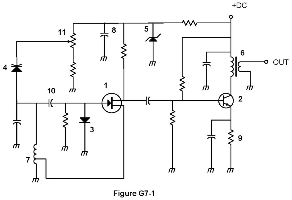
Which symbol in figure G7-1 represents a field effect transistor?
Figure G7-1
A Symbol 2
B Symbol 5
C Symbol 1
D Symbol 4
Show the answer and explanation
Correct answer: C. Symbol 1
Why C is right. C. Symbol 1 is the field effect transistor.
In figure G7-1, symbol 1 is a circle with a vertical bar inside. A line enters from the left with an arrow pointing toward the bar; that is the gate. Two lines leave the bar on the right; those are the drain and source. This is a junction FET, a transistor controlled by voltage on the gate.
Why not A? Symbol 2 is a circle with a slanted arrow on one lead, which marks a bipolar transistor, not a FET.
G7A10
Which symbol in figure G7-1 represents a Zener diode?
Figure G7-1
A Symbol 4
B Symbol 1
C Symbol 11
D Symbol 5
Show the answer and explanation
Correct answer: D. Symbol 5
Why D is right. D. Symbol 5 is the Zener diode.
In figure G7-1, symbol 5 is a triangle pointing at a bar, like a normal diode, but the bar has small bent tips at each end, like a stretched letter Z. A Zener diode holds a fixed voltage when current flows through it backward, so it is used as a voltage regulator.
Why not A? Symbol 4 has two lines at the bar, one curved, marking a varactor (a diode used as a tuning capacitor).
G7A11
Which symbol in figure G7-1 represents an NPN junction transistor?
Figure G7-1
A Symbol 1
B Symbol 2
C Symbol 7
D Symbol 11
Show the answer and explanation
Correct answer: B. Symbol 2
Why B is right. B. Symbol 2 is the NPN junction transistor.
In figure G7-1, symbol 2 is a circle with a vertical bar on the left side, which is the base. Two slanted lines leave the bar on the right. The lower one, the emitter, has an arrow pointing outward, away from the bar. An outward emitter arrow means NPN.
Why not A? Symbol 1 is a FET; its arrow is on the gate line pointing in, and it has no emitter.
G7A12
Which symbol in Figure G7-1 represents a solid core transformer?
Figure G7-1
A Symbol 4
B Symbol 7
C Symbol 6
D Symbol 1
Show the answer and explanation
Correct answer: C. Symbol 6
Why C is right. C. Symbol 6 is the solid core transformer.
In figure G7-1, symbol 6 shows two coils, each drawn as a row of loops, facing each other. Between them are two straight parallel lines. Those lines stand for a solid core of iron or ferrite that links the coils. A transformer with no core would show the coils with nothing between them.
Why not B? Symbol 7 is a single coil with a wire tapped off its middle, not two coils sharing a core.
G7A13
Which symbol in Figure G7-1 represents a tapped inductor?
Figure G7-1
A Symbol 7
B Symbol 11
C Symbol 6
D Symbol 1
Show the answer and explanation
Correct answer: A. Symbol 7
Why A is right. A. Symbol 7 is the tapped inductor.
In figure G7-1, symbol 7 is one coil drawn as a row of loops, near the bottom left of the drawing. A third wire leaves partway along the coil, between its ends. That connection is the tap. It lets a circuit use only part of the coil's turns.
Why not C? Symbol 6 has two coils with straight lines between them, which makes it a transformer.