Not affiliated with or endorsed by the FCC, NCVEC, ARRL or any VEC. Questions are the NCVEC pools word for word (public domain); explanations are our own. Exam rules and fees can change: check with your VE team.
E7D: Power supplies and voltage regulators; solar array charge controllers
Group E7D of the Amateur Extra pool (2024–2028) has 15 active questions. One of them is on every Amateur Extra exam. Each is shown word for word; open it to see the correct answer and our explanation.
E7D01
How does a linear electronic voltage regulator work?
A It has a ramp voltage as its output
B It eliminates the need for a pass transistor
C The control element duty cycle is proportional to the line or load conditions
D The conduction of a control element is varied to maintain a constant output voltage
Show the answer and explanation
Correct answer: D. The conduction of a control element is varied to maintain a constant output voltage
Why D is right. D. Feedback keeps the control transistor partly on and adjusts how much it conducts, so it drops whatever extra voltage would otherwise reach the output.
Think of the control element as a variable resistor in the supply path. If the load draws more or the input drops, feedback lets the element conduct more; if the output rises, it conducts less. The extra voltage is dropped across the element and turns into heat.
Why not C? Changing a duty cycle is how a switching regulator works.
E7D02
How does a switchmode voltage regulator work?
A By alternating the output between positive and negative voltages
B By varying the duty cycle of pulses input to a filter
C By varying the conductivity of a pass element
D By switching between two Zener diode reference voltages
Show the answer and explanation
Correct answer: B. By varying the duty cycle of pulses input to a filter
Why B is right. B. A switchmode regulator chops the input into pulses and adjusts their on-time, and a filter averages them into steady DC.
Duty cycle is the fraction of each cycle the switch is on. If the output sags, the controller widens the pulses; if it rises, it narrows them. An inductor and capacitor smooth the pulses into DC. Because the switch is always fully on or fully off, little power turns into heat.
Why not C? Varying how well a pass element conducts is the linear method.
E7D03
What device is used as a stable voltage reference?
A A Zener diode
B A digital-to-analog converter
C An SCR
D An analog-to-digital converter
Show the answer and explanation
Correct answer: A. A Zener diode
Why A is right. A. A Zener diode held in reverse breakdown keeps a nearly constant voltage across itself over a wide range of currents.
Most diodes are not meant to conduct backward. A Zener is built to break down at a set reverse voltage, such as 5.1 or 12 volts. Past that point, current can change a lot while the voltage barely moves, which makes it a handy reference for regulators.
Why not C? An SCR is a switch that latches on when triggered; it does not hold a fixed voltage.
E7D04
Which of the following describes a three-terminal voltage regulator?
A A series current source
B A series regulator
C A shunt regulator
D A shunt current source
Show the answer and explanation
Correct answer: B. A series regulator
Why B is right. B. A three-terminal regulator puts its pass transistor in series between input and output, so it is a series regulator.
Its three pins are input, output and ground or adjust. Inside are a voltage reference, an error amplifier and a series pass transistor that drops the extra voltage. A shunt regulator instead connects across the output and draws extra current.
Why not C? A shunt regulator sits across the load, not in line with it.
E7D05
Which of the following types of linear voltage regulator operates by loading the unregulated voltage source?
A A constant current source
B A series regulator
C A shunt current source
D A shunt regulator
Show the answer and explanation
Correct answer: D. A shunt regulator
Why D is right. D. A shunt regulator sits across the load and draws whatever current is needed to pull the source voltage down to the set value.
The source feeds a series resistor, and the shunt element connects from the output to ground. When the load takes less current, the shunt takes more, and the reverse. Total current through the resistor stays about the same, so the source is always loaded. A Zener diode with a resistor is the simplest example.
Why not B? A series regulator drops voltage in line with the load instead of loading the source.
E7D06
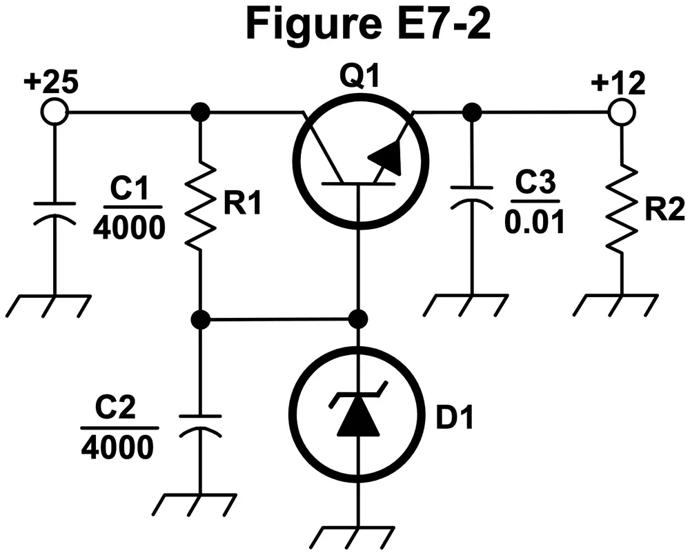
What is the purpose of Q1 in the circuit shown in Figure E7-2?
Figure E7-2
A It provides negative feedback to improve regulation
B It provides a constant load for the voltage source
C It controls the current to keep the output voltage constant
D It provides regulation by switching or “chopping” the input DC voltage
Show the answer and explanation
Correct answer: C. It controls the current to keep the output voltage constant
Why C is right. C. Q1 is the series pass transistor: it adjusts how much current it passes so the output holds at 12 volts as load or input changes.
In Figure E7-2, Q1 is the circled transistor with its collector on the +25 volt input line and its emitter, the lead with the arrow, on the +12 volt output line. Its base is held steady by Zener diode D1. The emitter follows the base, staying about 0.6 volt below it, so the output stays steady.
Why not D? Q1 conducts smoothly and never chops the input on and off, so this is not a switching circuit.
E7D07
What is the purpose of C2 in the circuit shown in Figure E7-2?
Figure E7-2
A It bypasses rectifier output ripple around D1
B It is a brute force filter for the output
C To prevent self-oscillation
D To provide fixed DC bias for Q1
Show the answer and explanation
Correct answer: A. It bypasses rectifier output ripple around D1
Why A is right. A. C2 sits across Zener diode D1 and smooths leftover ripple at Q1's base, so the reference voltage stays clean.
In Figure E7-2, C2 is the capacitor connected from the point where R1, D1 and the base of Q1 meet, down to ground. D1, the circled diode with a bent bar, also runs from that point to ground, so C2 is in parallel with it. Ripple at the base would pass through Q1 to the output; C2 shunts it to ground.
Why not B? C2 sits at Q1's base, not on the output line, and it is not the main filter; that job belongs to C1 at the input.
E7D08
What type of circuit is shown in Figure E7-2?
Figure E7-2
A Switching voltage regulator
B Common emitter amplifier
C Linear voltage regulator
D Common base amplifier
Show the answer and explanation
Correct answer: C. Linear voltage regulator
Why C is right. C. The circuit drops the extra voltage smoothly across a pass transistor controlled by a Zener reference, which is a linear regulator.
In Figure E7-2: C1 filters the +25 volt input, R1 feeds current to Zener diode D1, C2 smooths that reference, Q1 passes current from input to output, and C3 and load resistor R2 sit on the +12 volt output. Nothing switches on and off, and the roughly 13 volts across Q1 becomes heat.
Why not A? There is no inductor, oscillator or switching driver, so it is not a switching regulator.
E7D09
How is battery operating time calculated?
A Average current divided by capacity in amp-hours
B Average current divided by internal resistance
C Capacity in amp-hours divided by average current
D Internal resistance divided by average current
Show the answer and explanation
Correct answer: C. Capacity in amp-hours divided by average current
Why C is right. C. Amp-hours divided by amps leaves hours, so capacity over average current gives the run time.
An amp-hour is one amp flowing for one hour. A 20 amp-hour battery feeding an average of 4 amps lasts about 20 / 4 = 5 hours. Real batteries give somewhat less, since usable capacity drops at high current and in the cold.
Why not A? Current divided by capacity gives 1 over hours, the upside-down result.
E7D10
Why is a switching type power supply less expensive and lighter than an equivalent linear power supply?
A The inverter design does not require an output filter circuit
B The control circuitry uses less current, therefore smaller heat sinks are required
C The high frequency inverter design uses much smaller transformers and filter components for an equivalent power output
D It recovers power from the unused portion of the AC cycle, thus using fewer components
Show the answer and explanation
Correct answer: C. The high frequency inverter design uses much smaller transformers and filter components for an equivalent power output
Why C is right. C. Running the transformer at tens of kilohertz instead of 60 Hz lets it and the filter parts be much smaller and lighter.
A transformer moves a certain amount of energy each cycle. At a higher frequency there are many more cycles per second, so a far smaller core can carry the same power. Filter capacitors and inductors shrink too, because high-frequency ripple is easier to smooth. Less copper and iron means less weight and cost.
Why not A? Switching supplies still need output filters to smooth their pulses.
E7D11
What is the purpose of an inverter connected to a solar panel output?
A Reduce AC ripple on the output
B Maintain voltage with varying illumination levels
C Prevent discharge when panel is not illuminated
D Convert the panel’s output from DC to AC
Show the answer and explanation
Correct answer: D. Convert the panel’s output from DC to AC
Why D is right. D. Solar panels produce DC, and an inverter changes it to AC for household equipment or the power grid.
An inverter switches the DC on and off rapidly and shapes the result into an alternating waveform, often a 60 Hz sine wave. Holding the charging voltage steady as light changes, and stopping reverse discharge at night, are jobs for a charge controller and a blocking diode, not the inverter.
Why not B? Keeping voltage steady as sunlight changes is a charge controller's job.
E7D12
What is the dropout voltage of a linear voltage regulator?
A Minimum input voltage for rated power dissipation
B Maximum output voltage drop when the input voltage is varied over its specified range
C Minimum input-to-output voltage required to maintain regulation
D Maximum that the output voltage may decrease at rated load
Show the answer and explanation
Correct answer: C. Minimum input-to-output voltage required to maintain regulation
Why C is right. C. A linear regulator can only drop voltage, so once the input-to-output gap shrinks below this headroom the pass transistor is fully on and the output follows the input down.
A linear regulator needs some headroom to work. If a 12 volt regulator has 2 volts of dropout, its input must stay at 14 volts or more. Below that, the output falls along with the input. Low-dropout, or LDO, regulators need well under 1 volt.
Why not A? Dropout is about keeping regulation, not about power dissipation.
E7D13
Which of the following calculates power dissipated by a series linear voltage regulator?
A Input voltage multiplied by input current
B Input voltage divided by output current
C Voltage difference from input to output multiplied by output current
D Output voltage multiplied by output current
Show the answer and explanation
Correct answer: C. Voltage difference from input to output multiplied by output current
Why C is right. C. All the load current flows through the pass element, which drops the input-to-output difference, so its heat is that voltage times the current.
Power is voltage times current. For example, with 18 volts in, 12 volts out and 2 amps: (18 - 12) x 2 = 12 watts of heat in the regulator, while the load gets 12 x 2 = 24 watts. That wasted heat is why linear regulators need heat sinks.
Why not D? Output voltage times output current is the power delivered to the load, not the power lost in the regulator.
E7D14
What is the purpose of connecting equal-value resistors across power supply filter capacitors connected in series?
A Equalize the voltage across each capacitor
B Discharge the capacitors when voltage is removed
C Provide a minimum load on the supply
D All these choices are correct
Show the answer and explanation
Correct answer: D. All these choices are correct
Why D is right. D. Matched resistors across series capacitors balance their voltages, drain their stored charge and lightly load the supply, so every choice applies.
Capacitors in series split voltage according to their leakage, which varies, so one could get too much voltage and fail. Equal resistors force an even split. The same resistors drain the charge after power-off, protecting anyone who touches the supply, and their small steady current gives the supply a minimum load.
E7D15
What is the purpose of a step-start circuit in a high-voltage power supply?
A To provide a dual-voltage output for reduced power applications
B To compensate for variations of the incoming line voltage
C To prevent arcing across the input power switch or relay contacts
D To allow the filter capacitors to charge gradually
Show the answer and explanation
Correct answer: D. To allow the filter capacitors to charge gradually
Why D is right. D. A step-start circuit first feeds the supply through a resistor, limiting the surge while the large filter capacitors charge, then bypasses the resistor.
Empty capacitors act almost like a short circuit at switch-on. Without help, the surge can blow fuses, stress the rectifier diodes and strain the transformer. A series resistor limits that first rush of current; after a moment a relay shorts it out for normal operation.
Why not B? Changes in line voltage are handled by regulation, not by a start-up delay.