Not affiliated with or endorsed by the FCC, NCVEC, ARRL or any VEC. Questions are the NCVEC pools word for word (public domain); explanations are our own. Exam rules and fees can change: check with your VE team.

T6C: Circuit diagrams: use of schematics, basic structure; Schematic symbols of basic components

Group T6C of the Technician pool (2026–2030) has 12 active questions. One of them is on every Technician exam. Each is shown word for word; open it to see the correct answer and our explanation.

T6C01

What is an electrical diagram using standard component symbols called?

  1. A Connection chart
  2. B Instrumentation system
  3. C Schematic
  4. D Flow chart
Show the answer and explanation

Correct answer: C. Schematic

Why C is right. C. Schematic.

A schematic is a drawing of a circuit that uses standard symbols for each part, joined by lines that show the connections. Anyone who knows the symbols can read it, no matter how the real parts look.

Why not D? A flow chart shows the steps of a process, not electrical parts.

T6C02

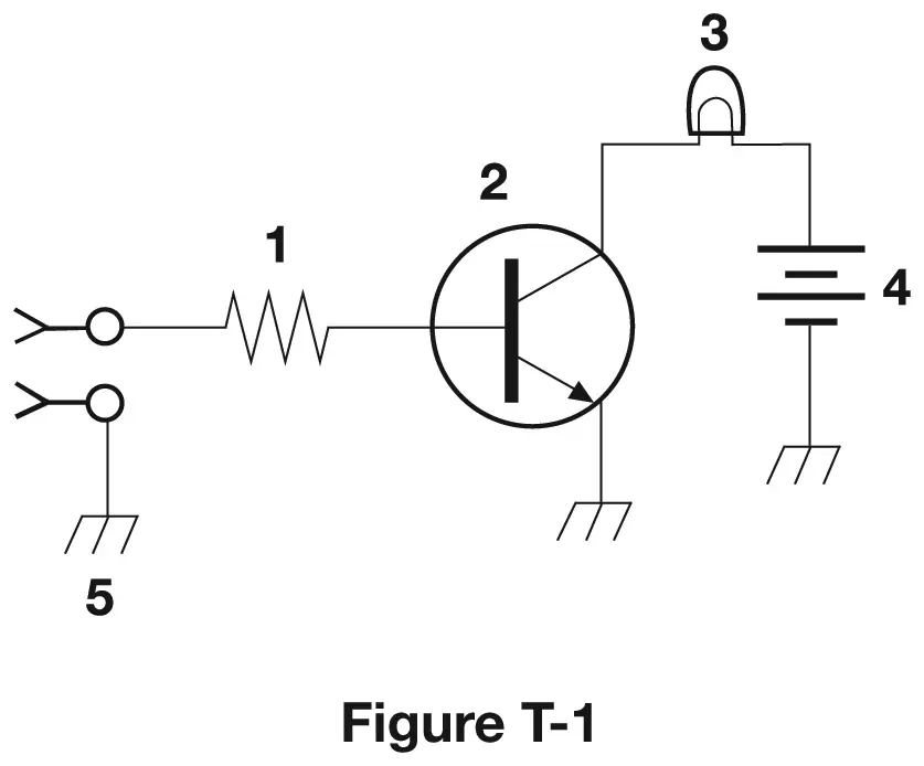
What is component 1 in figure T-1?

Figure T-1 is a simple transistor switch that lights a lamp. On the left are two input terminals, each drawn as a small open circle with a forked line, like a plug. The upper terminal connects through component 1, a zigzag line (a resistor), to the base of component 2. Component 2 is a circle containing a thick vertical bar with two slanted lines leaving it; the lower line carries an arrow pointing outward, marking the emitter of a bipolar transistor. The emitter goes down to a ground symbol. The upper slanted line, the collector, runs up to component 3, a small dome shape (a lamp), then across to component 4, a stack of alternating long and short lines (a battery), whose lower end goes to ground. The lower input terminal connects down to component 5, a line ending in short slanted strokes (a ground symbol).
Figure T-1
  1. A Resistor
  2. B Transistor
  3. C Battery
  4. D Connector
Show the answer and explanation

Correct answer: A. Resistor

Why A is right. A. Resistor.

Component 1 in figure T-1 is a zigzag line, the symbol for a resistor. It sits between the input connector and the transistor, limiting how much current reaches the transistor's base.

Why not C? A battery is drawn as alternating long and short parallel lines, like component 4.

Remember: Zigzag: the current has to work to get through.

T6C03

What is component 2 in figure T-1?

Figure T-1 is a simple transistor switch that lights a lamp. On the left are two input terminals, each drawn as a small open circle with a forked line, like a plug. The upper terminal connects through component 1, a zigzag line (a resistor), to the base of component 2. Component 2 is a circle containing a thick vertical bar with two slanted lines leaving it; the lower line carries an arrow pointing outward, marking the emitter of a bipolar transistor. The emitter goes down to a ground symbol. The upper slanted line, the collector, runs up to component 3, a small dome shape (a lamp), then across to component 4, a stack of alternating long and short lines (a battery), whose lower end goes to ground. The lower input terminal connects down to component 5, a line ending in short slanted strokes (a ground symbol).
Figure T-1
  1. A Resistor
  2. B Transistor
  3. C Indicator lamp
  4. D Connector
Show the answer and explanation

Correct answer: B. Transistor

Why B is right. B. Transistor.

Component 2 in figure T-1 is a circle with a thick vertical bar inside and two slanted lines leaving it. One slanted line has an arrow, which marks the emitter. That is the symbol for a bipolar transistor.

Why not C? The indicator lamp is component 3, the small dome shape above.

T6C04

What is component 3 in figure T-1?

Figure T-1 is a simple transistor switch that lights a lamp. On the left are two input terminals, each drawn as a small open circle with a forked line, like a plug. The upper terminal connects through component 1, a zigzag line (a resistor), to the base of component 2. Component 2 is a circle containing a thick vertical bar with two slanted lines leaving it; the lower line carries an arrow pointing outward, marking the emitter of a bipolar transistor. The emitter goes down to a ground symbol. The upper slanted line, the collector, runs up to component 3, a small dome shape (a lamp), then across to component 4, a stack of alternating long and short lines (a battery), whose lower end goes to ground. The lower input terminal connects down to component 5, a line ending in short slanted strokes (a ground symbol).
Figure T-1
  1. A Resistor
  2. B Transistor
  3. C Lamp
  4. D Ground symbol
Show the answer and explanation

Correct answer: C. Lamp

Why C is right. C. Lamp.

Component 3 in figure T-1 is a small dome or arch shape with a loop inside, sitting in the wire between the transistor and the battery. This is a lamp symbol. It lights when the transistor lets current flow.

Why not D? The ground symbol in figure T-1 is a line ending in short slanted strokes, like component 5.

T6C05

What is component 4 in figure T-1?

Figure T-1 is a simple transistor switch that lights a lamp. On the left are two input terminals, each drawn as a small open circle with a forked line, like a plug. The upper terminal connects through component 1, a zigzag line (a resistor), to the base of component 2. Component 2 is a circle containing a thick vertical bar with two slanted lines leaving it; the lower line carries an arrow pointing outward, marking the emitter of a bipolar transistor. The emitter goes down to a ground symbol. The upper slanted line, the collector, runs up to component 3, a small dome shape (a lamp), then across to component 4, a stack of alternating long and short lines (a battery), whose lower end goes to ground. The lower input terminal connects down to component 5, a line ending in short slanted strokes (a ground symbol).
Figure T-1
  1. A Resistor
  2. B Transistor
  3. C Ground symbol
  4. D Battery
Show the answer and explanation

Correct answer: D. Battery

Why D is right. D. Battery.

Component 4 in figure T-1 is a stack of parallel lines, alternating long and short. Each long-and-short pair is one cell, and the long line is the positive side. It supplies the power for the lamp.

Why not C? The ground symbol is component 5, short slanted strokes at the end of a line.

T6C06

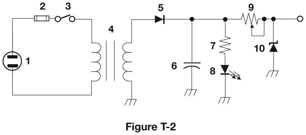
What is component 6 in figure T-2?

Figure T-2 is a DC power supply. Component 1, a circle with two short thick bars, is the AC source or plug. It connects in a loop through component 2, a small rectangle (a fuse), and component 3, a lever tilted between two open circles (a switch), to the left coil of component 4, two coils of loops with two straight lines between them (a transformer). The right coil's bottom goes to ground; its top feeds component 5, a triangle pointing right into a bar (a diode). After the diode, component 6, a flat plate over a curved plate (a capacitor), goes to ground. Component 7, a zigzag (resistor), feeds component 8, a downward triangle with two outgoing arrows (an LED), to ground. Component 9, a zigzag with an arrow (variable resistor), leads to the output, with component 10, an upward triangle under a bent bar (a Zener diode), to ground.
Figure T-2
  1. A Resistor
  2. B Capacitor
  3. C Regulator IC
  4. D Transistor
Show the answer and explanation

Correct answer: B. Capacitor

Why B is right. B. Capacitor.

Component 6 in figure T-2 is two short parallel plates, one flat and one curved, with a gap between them. It connects from the diode output to ground. Plates with a gap are the capacitor symbol, and here it smooths the pulsing DC.

Why not A? A resistor is drawn as a zigzag, like component 7.

T6C07

What is component 8 in figure T-2?

Figure T-2 is a DC power supply. Component 1, a circle with two short thick bars, is the AC source or plug. It connects in a loop through component 2, a small rectangle (a fuse), and component 3, a lever tilted between two open circles (a switch), to the left coil of component 4, two coils of loops with two straight lines between them (a transformer). The right coil's bottom goes to ground; its top feeds component 5, a triangle pointing right into a bar (a diode). After the diode, component 6, a flat plate over a curved plate (a capacitor), goes to ground. Component 7, a zigzag (resistor), feeds component 8, a downward triangle with two outgoing arrows (an LED), to ground. Component 9, a zigzag with an arrow (variable resistor), leads to the output, with component 10, an upward triangle under a bent bar (a Zener diode), to ground.
Figure T-2
  1. A Resistor
  2. B Inductor
  3. C Regulator IC
  4. D Light emitting diode
Show the answer and explanation

Correct answer: D. Light emitting diode

Why D is right. D. Light emitting diode.

Component 8 in figure T-2 is a triangle pointing down onto a bar, the diode symbol, with two small arrows pointing away from it. The outgoing arrows mean the diode gives off light. It glows when the supply is on.

Why not C? A regulator IC is usually drawn as a box with labeled pins.

T6C08

What is component 9 in figure T-2?

Figure T-2 is a DC power supply. Component 1, a circle with two short thick bars, is the AC source or plug. It connects in a loop through component 2, a small rectangle (a fuse), and component 3, a lever tilted between two open circles (a switch), to the left coil of component 4, two coils of loops with two straight lines between them (a transformer). The right coil's bottom goes to ground; its top feeds component 5, a triangle pointing right into a bar (a diode). After the diode, component 6, a flat plate over a curved plate (a capacitor), goes to ground. Component 7, a zigzag (resistor), feeds component 8, a downward triangle with two outgoing arrows (an LED), to ground. Component 9, a zigzag with an arrow (variable resistor), leads to the output, with component 10, an upward triangle under a bent bar (a Zener diode), to ground.
Figure T-2
  1. A Variable capacitor
  2. B Variable inductor
  3. C Variable resistor
  4. D Variable transformer
Show the answer and explanation

Correct answer: C. Variable resistor

Why C is right. C. Variable resistor.

Component 9 in figure T-2 is a zigzag line, the resistor symbol, with an arrow pointing into it from below. The arrow is a sliding contact, which makes the resistance adjustable.

Why not B? A variable inductor would be a row of coil loops with an arrow, not a zigzag.

T6C09

What is component 4 in figure T-2?

Figure T-2 is a DC power supply. Component 1, a circle with two short thick bars, is the AC source or plug. It connects in a loop through component 2, a small rectangle (a fuse), and component 3, a lever tilted between two open circles (a switch), to the left coil of component 4, two coils of loops with two straight lines between them (a transformer). The right coil's bottom goes to ground; its top feeds component 5, a triangle pointing right into a bar (a diode). After the diode, component 6, a flat plate over a curved plate (a capacitor), goes to ground. Component 7, a zigzag (resistor), feeds component 8, a downward triangle with two outgoing arrows (an LED), to ground. Component 9, a zigzag with an arrow (variable resistor), leads to the output, with component 10, an upward triangle under a bent bar (a Zener diode), to ground.
Figure T-2
  1. A Variable inductor
  2. B Double-pole switch
  3. C Potentiometer
  4. D Transformer
Show the answer and explanation

Correct answer: D. Transformer

Why D is right. D. Transformer.

Component 4 in figure T-2 is two coils of loops facing each other with two straight lines between them. Each coil is a winding, and the lines show an iron core. Power moves from one winding to the other through the shared magnetic field.

Why not C? A potentiometer is a zigzag with an arrow, like component 9.

T6C10

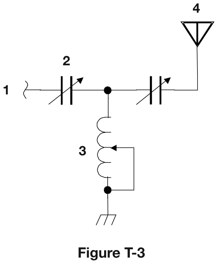
What is component 3 in figure T-3?

Figure T-3 is an antenna tuner. On the left, component 1 is a wavy line marking where the feed line from the radio connects. It runs right through component 2, two short parallel plates with a slanted arrow across them (a variable capacitor), to a junction dot. From that dot, a second variable capacitor of the same shape, unnumbered, continues right and then up to component 4, an upside-down triangle with a vertical line through it (an antenna). Also from the junction dot, a wire goes down to component 3, a vertical row of coil loops with an arrow touching the coil partway down (a variable inductor). The arrow's wire wraps around to a second dot at the bottom of the coil, which connects down to a ground symbol, a line ending in short slanted strokes.
Figure T-3
  1. A Connector
  2. B Meter
  3. C Variable capacitor
  4. D Variable inductor
Show the answer and explanation

Correct answer: D. Variable inductor

Why D is right. D. Variable inductor.

Component 3 in figure T-3 is a row of coil loops, the inductor symbol, with an arrow touching the coil partway down. The arrow is a movable tap, so the amount of coil in use can be changed. That makes it a variable inductor.

Why not C? A variable capacitor is two parallel plates with a slanted arrow, like component 2.

T6C11

What is component 4 in figure T-3?

Figure T-3 is an antenna tuner. On the left, component 1 is a wavy line marking where the feed line from the radio connects. It runs right through component 2, two short parallel plates with a slanted arrow across them (a variable capacitor), to a junction dot. From that dot, a second variable capacitor of the same shape, unnumbered, continues right and then up to component 4, an upside-down triangle with a vertical line through it (an antenna). Also from the junction dot, a wire goes down to component 3, a vertical row of coil loops with an arrow touching the coil partway down (a variable inductor). The arrow's wire wraps around to a second dot at the bottom of the coil, which connects down to a ground symbol, a line ending in short slanted strokes.
Figure T-3
  1. A Antenna
  2. B Transmitter
  3. C Dummy load
  4. D Ground
Show the answer and explanation

Correct answer: A. Antenna

Why A is right. A. Antenna.

Component 4 in figure T-3 is an upside-down triangle with a vertical line through it, sitting on top of a wire. That is the antenna symbol. The circuit below it adjusts the match between the radio and this antenna.

Why not D? Ground is drawn as short slanted strokes, shown at the bottom of the coil.

T6C12

Which of the following is accurately represented in electrical schematics?

  1. A Wire lengths
  2. B Physical appearance of components
  3. C Component connections
  4. D All these choices are correct
Show the answer and explanation

Correct answer: C. Component connections

Why C is right. C. Component connections.

A schematic shows which parts connect to which. It does not show real wire lengths, part sizes or where parts sit on a board. Two parts drawn far apart might be next to each other in the real device.

Why not B? Symbols are standard shapes, not pictures of how parts look.